Antenna coil is one of the main components that enables communication in a RFID system. In some cases, it also serves to harvest electricity from alternating electromagnetic fields and supply electrical power to a RFID device. Ideally, designing and developing an antenna coil for use should be relatively easy. However, particular physical constraints such as shape, size, available space and mutual inductance could made design and development harder. In this article, we will be discussing particular aspect of designing a 13.56MHz antenna for Near Field Communications (NFC).
A RFID IC can extract all of its power from alternating magnetic fields generated by the coupled Proximity Coupled Reader (PCR) in order to both operate and communicate with the PCR. Ampere’s law states that an alternating current flowing within a transmission antenna coil radiates an alternating magnetic field around the coil conductor. Faraday’s law states that the alternating magnetic field through a plane bounded by a closed conductor loop of a receiving antenna coil induces a voltage in the loop. The receiving antenna coil of a RFID IC acts like the secondary coil of a transformer where both AC current and voltage are induced in its coil when the alternating magnetic field passes through. The induced AC voltage is rectified to provide a DC voltage source for the RFID IC. Once the DC voltage reaches a certain level, the RFID IC starts to operate. An efficient transfer of energy from the PCR to the RFID IC helps to improve the operational reliability and read range.
The designs of both respective antenna coils of the RFID IC and the PCR have a significant effect on the energy transfer and communication range, and could depend at least on a number of electrical parameters such as, for example, Q factor, resonant frequency, mutual inductance, and power. In this article, we will illustrate the effect of varying the Q factor on the read range in a RFID system.
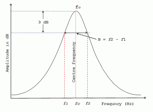
Q-factor, or quality factor, characterizes how under-damped a tuned LC resonator circuit of the antenna coil is. It is based on a ratio of the resonant frequency (i.e., “fc”) and its 3dB bandwidth (i.e., “B”). Technically, it is the ratio of the stored energy of the LC resonator circuit to discharged energy. In a RFID system, the magnetic coupling between the primary winding (e.g., PCR antenna coil) and the secondary winding (e.g., tag or transponder antenna coil) transfer power from the PCR to the RFID tag. The tuned LC resonator circuits of the windings at the resonant frequencies maximize magnetic coupling between the primary and secondary windings. An antenna coil with higher Q-factor resonates with higher amplitudes and therefore allows the RFID system to communicate at longer read range. In other words, a higher Q-factor allows the RFID tag or transponder to extract and store more energy from the coupled magnetic fields emitted by the PCR. However, a higher Q-factor could also indicate a smaller 3dB bandwidth. A smaller 3dB bandwidth may cause the RFID tag (or transponder) to be more susceptible to changes in tuning of its antenna coil caused by such as, for example, manufacturer tolerances of the antenna coil, mutual inductance caused by one or more inductors (e.g., RFID antenna coil or metallic conductor) within proximity of the RFID tag.
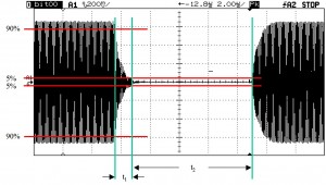
At the electrical level, changes in the Q-factor of an antenna coil could affect the read range of a RFID system. For example, for the RFID system to be within sustainable operating read range, time t2 (i.e., time between transmitting pulses) of a RFID transmitter (e.g., PCR) should satisfy min and max timing requirements. If time t2 is above the maximum limit, then its Q-factor value is too low and has to be increased. If time t2 is below the minimum limit, then its Q-factor is too high (e.g., PCR generates too much power and may be beyond government limits) and needs to be reduced.
If you have any questions, please feel free to contact us.


